A couple months back, I decided to dive into some basic electronics and where better to start than the beloved 555 Timer IC ¯\_(ツ)_/¯. Being a strong believer of project-based learning, I decided to make a project using the timer instead of just cramming up the theory. Fast forwarding a couple weeks, here I present to you 555 Timer based Servo Tester 🎉
555 Timer Servo Tester in action. Here I am controlling the base joint servo of a robotic arm & drive servo for a linear actuator mechanism on one of my mobile robots.
In this blog, I would like to share some interesting problems I faced and their solutions. But first, let’s start with the basics.
How Servo Motors Work
A servo motor is a motor which can be moved to a particular angle. Internally, the servo uses a closed loop system to control the position of the shaft. Like any other closed loop system, this system also needs a feedback (position feedback in this case) to control the output. This is achieved with the help of a potentiometer.
But how dow you send angles as commands to the servo?
Well, a servo has 3 wires 2 of which are obviously VCC and GND for powering the internal DC motor. The third wire is where the magic happens. The third wire is the signal wire where you provide a PWM (Pulse Width Modulated) signal to get different angles. The relation between PWM signal and servo angle can be seen in the table below.
| Servo Angle (degrees) | Signal On Time (ms) | Period (ms) | Duty Cycle (%) | |
|---|---|---|---|---|
| 0 | 1 | 20 | 5 | |
| 90 | 1.5 | 20 | 7.5 | |
| 180 | 2 | 20 | 10 |
Note: The above values are all ideal. In reality, I have even noticed the duty cycle for some servos to range from 2% to 14%!
So from this information we can conclude that to move a servo all we need is some power and a PWM signal. So how do we do that? We use the 555 Timer 😎
Note: We could also use a controller or a development board like arduino for this. Heck they even have in-built libraries so you don’t even have to write the code that generates the PWM signal according to the above table. You just pass the angle to the
servo.write()function and sit back while the library does its magic. But, where’s the fun in that :p
555 Timer and its Different Modes
The 555 Timer IC is a cheap and precise timing IC that can be used to generate various kinds of clock or PWM signals. The 555 timer can be used in following modes:
- Monostable Mode: In this mode, the output of the 555 timer is driven high for a fixed time when an input trigger is detected. This mode, therefore, contains a single stable output state - hence the name ‘Monostable’. Know more about this mode here
555 Timer in Monostable Mode. The output turns ON for about 1.1s when switch is closed & Trig is pulled to GND. While the output is ON it completely ignores the Trig input.The circuit on Multisim can be found here
- Bistable Mode: In this mode, the output of the 555 timer is driven high when the input trigger is detected and driven low when reset is driven low. This mode, therefore, contains 2 stable output states - hence the name ‘Bistable’. Know more about this mode here
555 Timer in Bistable Mode. The circuit uses a SPDT switch to connect either pin TRIG or RESET to GND. This accordingly turn the LED on or off.The circuit on Multisim can be found here
Note: After seeing the gif above you might be wondering why go through all that trouble? Just use a switch :| Well, the answer is in ‘Debouncing’. See, when we use mechanical switches, the signal passing through them bounces when the contacts touch or separate. This can sometimes be a problem for your circuit as it might give false positives. Since this circuit uses the internal SR-Latch flip flop of the 555 Timer, it ignores the bouncing of the switch and gives us a stable output. This ‘debounced’ output is really important for timing applications. Do watch the linked videos for more clarity about this.
- Astable Mode: In this mode, the output of the 555 timer generates a square wave without any intervention from the user. The square wave is infact a PWM signal whose duty cycle can be adjusted by changing the values of the timing capacitors and resistors. Know more about this mode here
555 Timer in Astable Mode. The circuit uses a potentiometer to change the pulse width or the duty cycle of the output signal. We can see the LED pulsing in the output.The circuit on Multisim can be found here
‘Stable’ in all modes above simply means that the output will tend to stay in that state until an input trigger is detected. In ‘Monostable’ there is a single stable state which is the default state of the output and the output can be taken out of that state with the input trigger. In case of ‘Bistable’, both states of the output are considered stable and you can switch between them using 2 different input triggers. The ‘Astable’ mode however, does not have any stable state and just gives a square wave on the output.
Operating Servos with 555 timer in Astable Mode
Since the Astable mode of operation provides us with a PWM signal at the output, its pretty obvious that we can use it to operate servos.
We can even replace one of the timing resistors with a potentiometer to control the duty cycle of the PWM output and get a full sweep of motion from the controlled servo.
Simple, right? Well sadly, its not that straight forward :/
The Problem with Generic Astable Mode
Let’s first have a closer look at the circuit of a 555 Timer in ‘Generic Astable Mode’. Why ‘Generic’? Because this the circuit you will see most of the times when looking for 555 timer in astable mode.
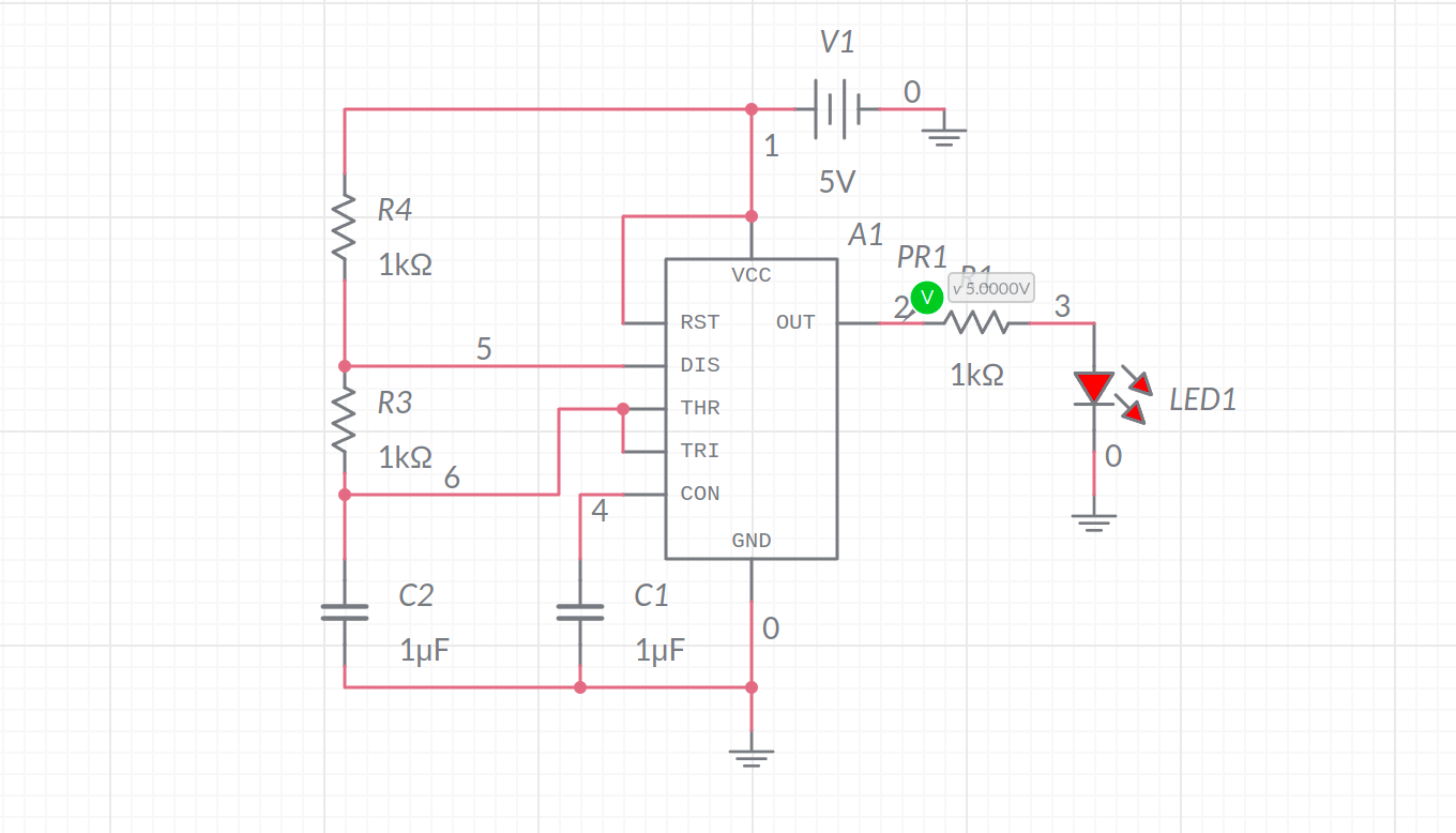
555 Timer in Astable Mode
Here, the values of the resistors $R3$ & $R4$ and capacitor $C2$ determine the on time and off time of the PWM output. Therefore, we can control the duty cycle of the PWM output if we add a variable resistor in the mix (like done in the above gif). But to make explanations easier lets omit the potentiometer for now. In the circuit above, the on time & off time can be calculated as follows:
$$T_{high}=0.693 * (R3 + R4) * C2$$
$$T_{low}=0.693 * R3 * C2$$
$$T_{period}=0.693 * (R4 + 2R3) * C2$$
From the above equations we can easily see,
$$T_{high} > T_{low}, \ always$$
Since, the duty cycle of a PWM signal is the percentage of the time for which the signal was high during a time period, we can easily infer that $ Duty\ Cycle (\%) > 50%$.
The culprit here is $R3$. Since both, the charging & discharging currents, flow through $R3$, the charging time can only go as low as the discharging time. Therfore, the duty cycle can only go as low as $50\%$.
And that friends, is the problem. As discussed before: A servo works with a PWM signal whose duty cycle ranges from $5 - 10\%$! in ‘ideal situations’ (which we all know does not exist).
So, what about the solution? Well, stay tuned for that ;)
$Spoiler Alert:$ This problem can be $Rectified$ ;)