
If you are like me, you want RGB lights in everything. Be it your mouse, your keyboard, or heck even your room. Therefore, to fulfill this colorful need, I started working on a project to install the addressable WS2812B LEDs to the shelves in my room. The plan was simple: use an ESP8266-based board (specifically the Wemos D1 Mini) with WLED installed as the main controller, hook it up the LEDs and use the WLED Android App to control the LEDs.

If you are interested in making the project yourself, you can go through and follow the steps in my Instructable.
So as with any project, I hopped on the Delhi metro, arrived at the local market and bought all the required stuff including the LED Strip, Wemos D1 Mini board, an IRF540N n-channel MOSFET, some JST Connectors and screw terminals etc.
Anyways, back to the story. So, after getting all the stuff I returned home, connected the Wemos D1 Mini to my laptop, selected the correct port in Arduino IDE and uploaded the blink LED sketch to test the board. Aaaaand it didn’t work 🥲
Upon close inspection, I found some weird stuff going on with the board!! And with that came a realization…
Never Blindly Trust the Stuff You Buy#
So here’s the problem: Whenever the board is connected, a serial port shows up in the Arduino IDE but no matter what, you cannot upload any code to it. Even dmesg shows that it is loading a driver for the FT232RL USB-to-UART Chip!
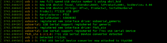
Even the windows device manager does the same: assigns FT232 drivers for the device but the result is still the same. We can see the idVendor in the dmesg output as 0403 and a quick google search shows that this Vendor ID indeed belongs to FTDI (this is the company that manufactures the FT232RL chip). But here’s the catch:
If you read the Official Wemos Documentation for the D1 mini, it shows that the board uses CH340 as the USB-to-UART Converter not the FT232R! 😵💫
Sooooo, what the hell is happening here?
To find some answers I turned to the board specifically to see if it was actually using the FT232. And guess what? The name of the IC is erased off…🥲 Believe me when I say this does not end here. It gets better.
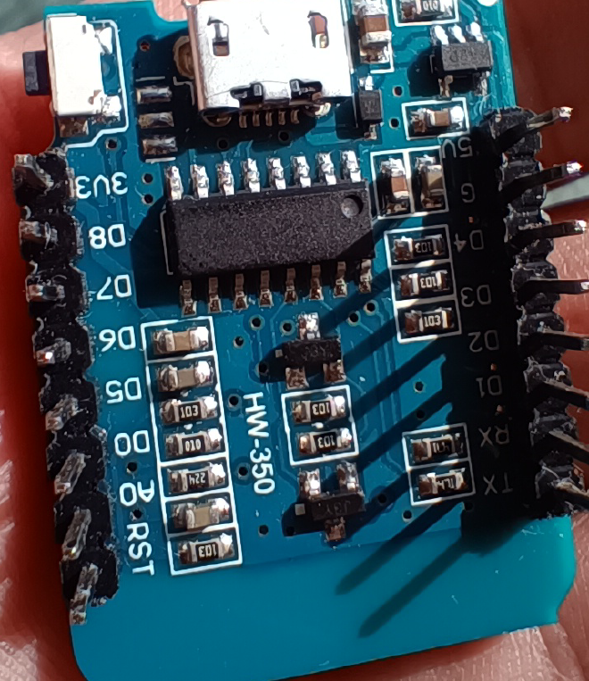
I opened up the pinout of FT232R and the CH340 side by side, powered the board and started probing some pins with my multimeter to see which pinout it matches. Aaanddd…drum rolls please…it matches the pinout of the CH340 IC!! So, it is indeed CH340 but it acts like FT232R causing the OS to load the wrong drivers and resulting in the board not working.

So people, that’s why you should never completely trust the stuff you buy locally. As for me, I kept the board aside for further investigations and turned to next closest thing to an ESP-based board I had at the ready. This turned out to be the Bolt IOT Wifi Module which I had bought about 3 years back but never used once.
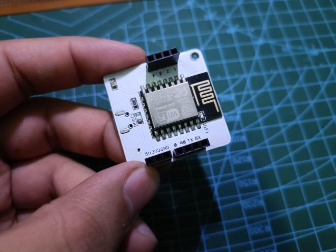
If I had this, then why didn’t I go with it in the first place? Well, because although the WEMOS D1 Mini and Bolt IOT wifi module both use the same ESP-12E at its core, there is a big difference. While the Wemos D1 Mini is a developement board and can be programmed through USB for any application, the Bolt IOT Wifi Module is, in fact, a module. It comes pre-flashed with some code that allows you to program it through the Bolt IOT cloud platform (or app) or you can hook it up to an Arduino as a wifi module. The module itself does not have any USB-to-UART Converter on board. In my opinion, this feels like of a waste of capability of the ESP-12E module as it prevents standalone use of the board which I wanted in my case. So, let’s see how I worked my way around this.
The ESP-12E Bootloader Modes & How it gets Programmed#
To understand how I used the Bolt IOT Wifi Module for this, we first need to understand the bootloader modes of the ESP-12E module. When we power up the ESP-12E module, there are 3 different modes the moduel can enter:
- Normal Mode
- UART Programming Mode
- SD-Card Boot
Here we only care about the Normal Mode and the UART Programming Mode. Normal Mode or the Flash Start-up Mode, as the name suggests, loads the program saved in the module’s internal flash and starts executing it. This is mode we are most familiar with. The UART Programming Mode is the one which allows you to upload a new program to the module’s flash memory through UART. The bootloader which gets selected when the device powers up or is reset, depends on the state of some of the GPIOs. Below you can find a table that shows the required GPIO states for different bootloader modes.
| Bootloader Mode | GPIO 0 | GPIO 2 | GPIO 15 | |
|---|---|---|---|---|
| Normal Mode | 1 | 1 | 0 | |
| UART Programming Mode | 0 | 1 | 0 | |
| SD Card Boot | 0 | 0 | 1 |
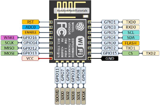
From the table above, we can easily infer that the state of GPIO 0 is the main deciding factor for our desired bootloader modes as the other two GPIOs have the same state in both cases. Apart from this, if the RESET pin gets connected to GND, the board resets and again selects the bootloader mode accroding to the states of the above GPIOs. Below you can find a pinout diagram of ESP-12E for reference.
So basically this is what we need to do to make the ESP-12E on the Bolt IOT Module Programmable:
- Pull
GPIO 2up - Pull
GPIO 15down - Have some sort of mechanism to change the state of
GPIO 0as required - Have a push button connected to the
RESETpin that connects itGNDwhen pressed
Upon inspecting the ESP12-E on the Bolt IOT Module these are the things I found:
RESETPin was left floatingGPIO2was left floatingGPIO15was connected to the GND PlaneGPIO0was left floating. Since the board already had a program flashed for OTA (over the air) uploads they don’t need the GPIO0
Making the ESP-12E on the Bolt IOT Module Programmable#
So from the above points I knew I had to only:
- Connect
GPIO2to VCC through a pull up resistor - Connect a push button to
RESETthat connects it toGNDwhen pressed. We can name this the ‘Reset’ button. - Connect a
GPIO0to a push button that connects it toGNDwhen pressed. We can name this the ‘Boot’ button. - Have a 6 Pin female header that exposes the
TX,RXandGNDpins for connecting an external USB-to-UART Converter Module to program the module
Here’s a schematic of how this was done:
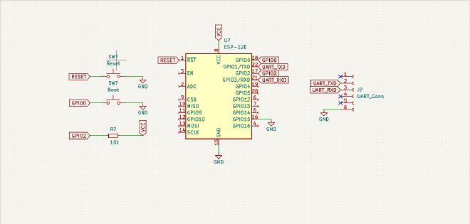
Once this is done, to program the mode we can simply press the Boot button and then reset the board using the Reset button. This will send the board in the Programming Mode and then we can hook up the external USB-to-UART module and upload a program to the board!
Note: You might have seen the same two buttons (Reset and Boot) on some ESP-based boards like the NodeMCU or ESP32. These work on the same principle.
Note: You also might have noticed that you don’t have to do play with these buttons everytime on a board like the NodeMCU. Heck the Arduino UNO does not even have a
Bootbutton. So, how are they changing the bootloader modes? This is where the USB-to-UART IC comes in. It automatically sends some signals to the required pins and changes the bootloader modes when you press the upload button on your Arduino IDE.
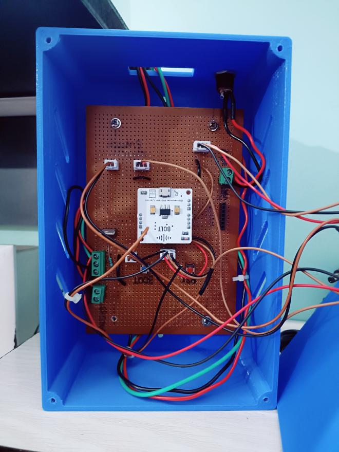
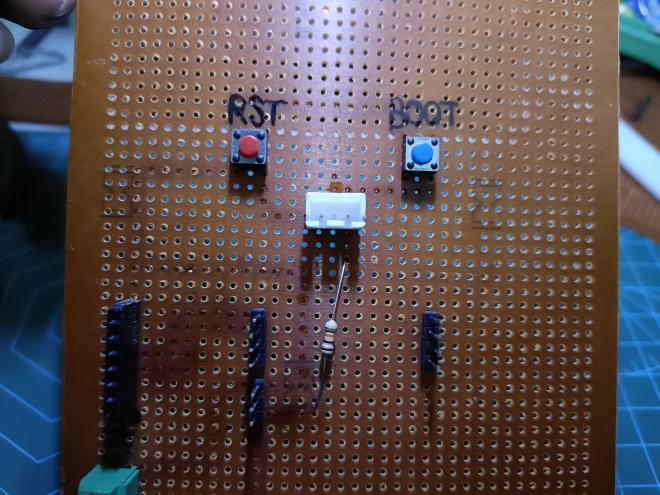
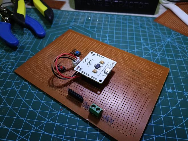
Here are some photos of the final soldered setup on a perf board for the final project:
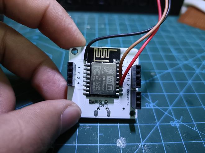
And here are some images of the final project: